
Design criteria
The design starts with the customer's expectations, the thermal duty, the fluid conditions and the operating environment. Site restrictions and project obligations are reviewed with the technical requirements.
Engineering
Thermal duty is only the starting point. Installation, materials, airflow and sound are solved together.
Design software
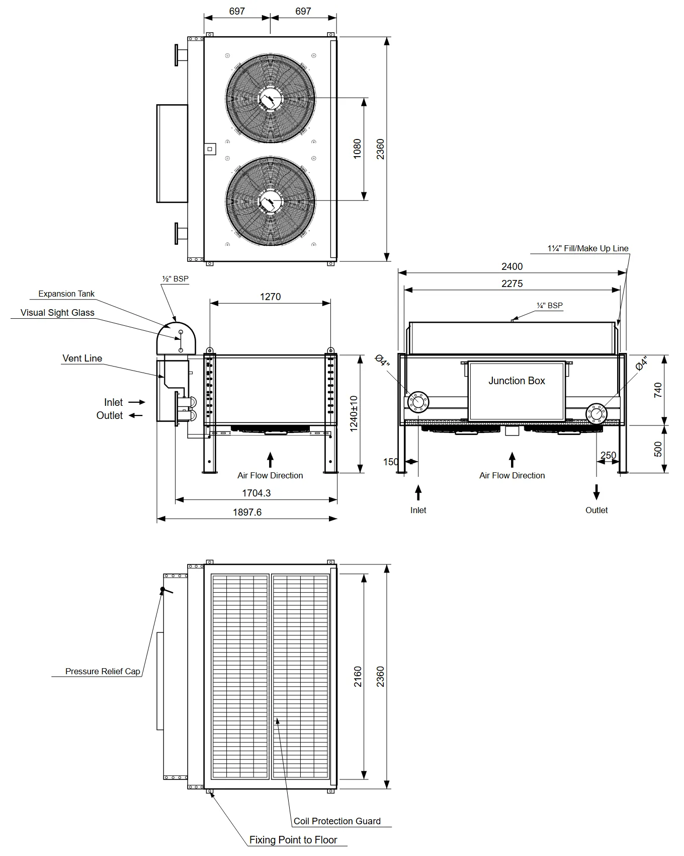
Coil geometry, fin pitch, rows and passes, fan selection and sound level are solved together against the duty and the site ambient. The same tool draws the datasheet sketch and the general arrangement drawing, so the drawing you receive is the unit that was calculated.
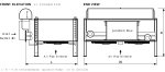
The design starts with the customer's expectations, the thermal duty, the fluid conditions and the operating environment. Site restrictions and project obligations are reviewed with the technical requirements.
Heat exchange area, overall dimensions and fan arrangement are selected for the heat load and the ambient. Transport limits, support points and maintenance access define the layout.
Tube and fin materials, fin coating, casing material and paint are chosen for the site atmosphere: dusty, marine, offshore and other demanding conditions.
Fan and motor selection follows the airflow, the pressure drop and the ambient temperature; the sound limit is evaluated at the same stage. Speed control, fan diffusers and silencers are offered where needed.
Expansion tanks, level switches, control panels, oil and fuel coolers and plate heat exchangers are considered with the main exchanger for one coordinated system.
Where the installation requires it, CFD studies of airflow and recirculation and structural analysis of frames and supports verify the equipment under the project loads.
Analysis & verification
Computational fluid dynamics of the air inlet and discharge paths, nearby obstructions and recirculation for cooler banks and tight installations.
Finite element evaluation of frames, casings and support arrangements under wind, seismic, transport and operating loads.
Dimensional and interface checks, pressure and leak tests of every circuit, fan and electrical function tests, and performance or acoustic verification where specified.
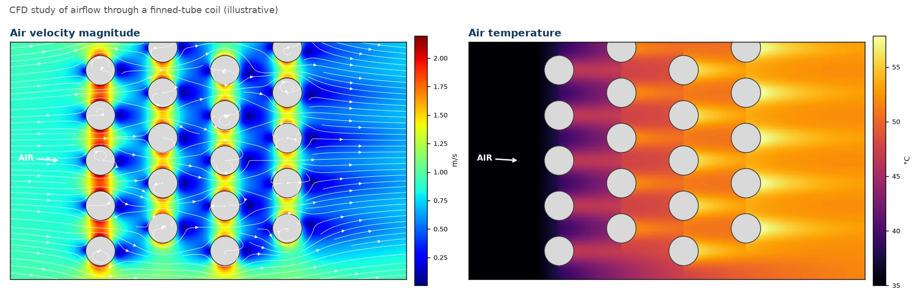
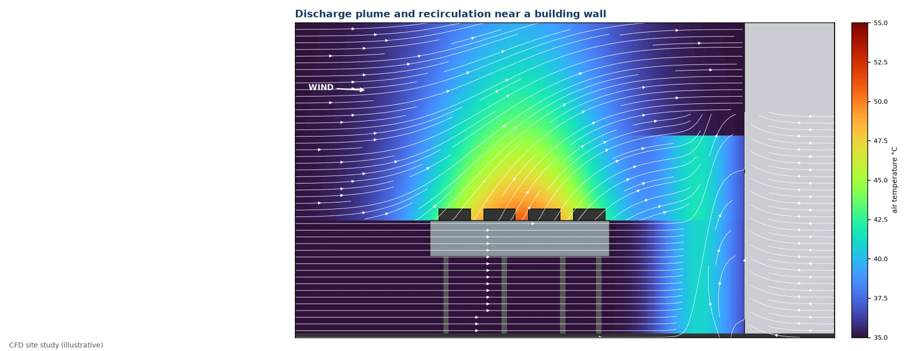
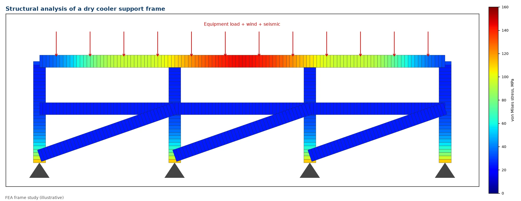
CFD and FEA images are illustrative; project studies are delivered with the model assumptions, load cases and results for the specific equipment.
Duty, ambient and system interfaces
Thermal design, airflow and structure
Layout, materials and connections
Agreed checks, acceptance criteria and records
Send us the heat duty, the fluid temperatures and flow rates, the ambient conditions and the installation limits. We answer with a design proposal.